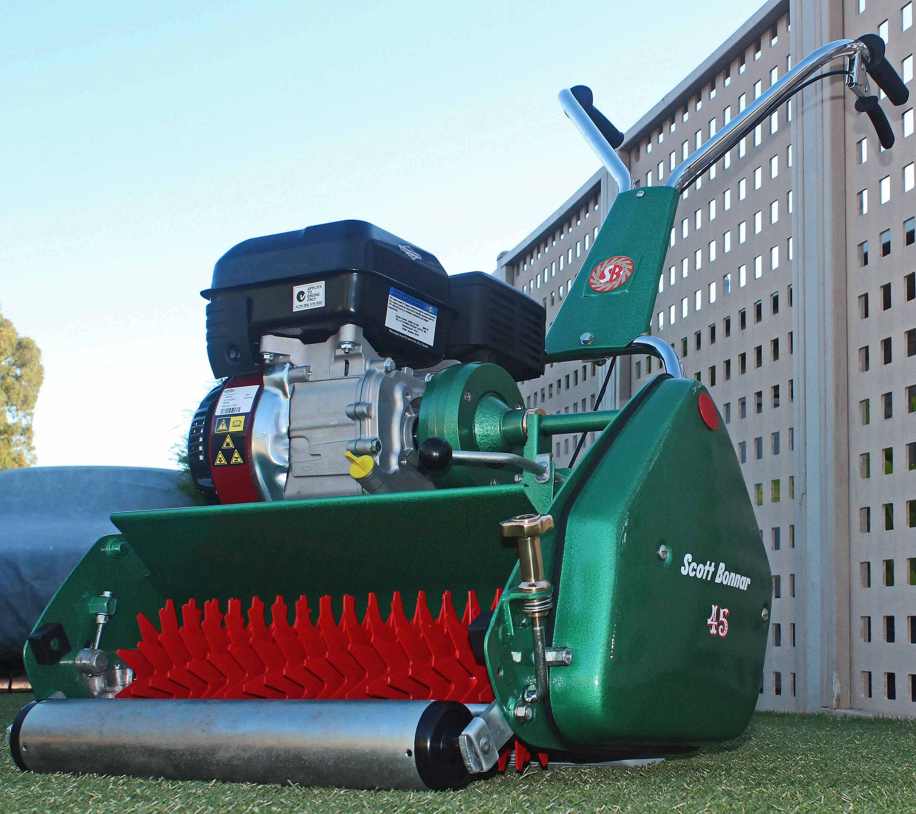
I am new to this forum, but have used it a lot to help me with my first Scott Bonnar restoration. Thought I would post a few pictures and comments from my restoration in case they might help others going through the same process.
Attached are a couple of pictures of the mower I bought to restore - you will notice it is actually in pretty good shape already, however being new to Scott Bonnar I didn't want to take on something overly difficult.
More through luck than good judgement, some of the things the mower had when I bought it that I am now appreciative of are no cracks in the top rails, the catcher and coverplate for the gears/chains are both straight with little or no dents, and the handlebars are relatively corrosion free.
I will provide updates as I go, just for general interest.
It's been rather quiet on the Model 45 front with winter being the attributing factor there.
What you have there is someone else's handy work that's been there before you. That being said it certainly sounds like this will keep the costs down for you in the long run, nevertheless the work load isn't any shorter though as it will be a total strip down and refurbishment, but hopefully this time done properly.
Chain and sprocket wise this one certainly looks good, but the proof will be revealed on the tear down.
Please keep us up to date with plenty of images and don't hesitate to write if you have any issues.
Cheers, BB.
I live a 24 Hour lifestyle, but every now and again I seem to fall asleep, well at least that's what my wife tells me.
Yes, certainly someone has put some effort in to it beforehand, so lets hope that keeps the cost down a little as you say!
I have actually been doing the project for about a month now, bit by bit, but only just really had time to start posting it.
Attached are a few more photos of the strip down and what I found as I went.
Mostly it came apart with no issues - the only bit that was a little difficult were the reel height adjuster screws - it appears they had been spray painted at some stage, so it was difficult to get them moving again. Still, with a little perseverance they came loose eventually.
I read somewhere on this forum about a gear puller from Supercheap, so I invested $40 in one - that made life a lot easier for getting gears and old bearings off. Thanks to whoever posted that tip!
One thing I did as I was overwhelmed with all the gears / chains etc when I opened it up was number the chains so i knew where they went back - nerdy I know, but still I hope it saves a bit of time when putting all back together again.
As you can see, I didn't strip it back to bare metal, but went over it with 240 grit sandpaper instead.
Since then I have painted all the parts - I sanded it back with 240 grit sandpaper, and then used Hammerite Metal Paint - Hammered Finish in dark green.
Another tip I read on a post (thanks to whoever posted it) was to use a roller for the bigger areas - this worked a treat!
The paint job is okay, but not great - don't zoom in too close on the photo's......
Thanks Jack - I will keep providing pictures and and comments as I go. Hopefully it is useful information to make public.
Attached are a few more pictures as I have started cleaning components up, and am now in the early stages of the build.
I bought a few new parts, more for aesthetics than functionality. The parts I bought include: - New front roller and bracket. I have included a picture of this as I think the bracket is genius - bought from SBF&P on Ebay. The bracket has an angle in it which makes higher cut heights possible. Once I have the bed knife re-installed I will measure the upper and lower cut limits for cut height. - New clutch fork set - New bolt kit - New corks (thanks for glueing tip Deejay - worked really well. I used the Sellley's Kwik Grip Gel for vertical surfaces (no drip), and then used clamps to keep them under pressure while they dried - I thought I took a photo, but can't find it...) - New reel and motor drive bearings
For the gears, I just sanded them back with some 240 grit sandpaper.
I've just looked back at this thread to see it's progress and have noticed a part that's been flogged out and definitely requires replacement.
The part is the Transfer Shaft that fits into the primary clutch and provides drive over to the drive train. If you look closely at it you'll see the end of it has been worn away to a bit of a taper. This will have the clutch cone oscillate inside the outer clutch half which in turn will have the clutch rendered useless as it will start to grab after a few moments of it being disengaged.
This becomes a dangerous situation as when you disengage the clutch you WANT it to be disengaged and not suddenly start to provide drive to the drive train gear.
You can get one of these from George in Adelaide where you've gotten the other parts from.
Cheers, BB.
I live a 24 Hour lifestyle, but every now and again I seem to fall asleep, well at least that's what my wife tells me.
Thanks BB - that makes a lot of sense. Before doing the strip down it wasn't possible to disengage the reel, it was always engaged regardless of what position the clutch lever was in. I thought it was the cork, so I replaced that - however on reflection the cork might have been worn, but wasn't irregular or have any high spots.
I will order a new clutch drive shaft (I assume this is the same as the transfer shaft, just a different name).
Yes it's the same part just my take on it as it transfers the drive from the engine to the drive train section of the machine.
If I recall correctly George has the cheapest unit out there on the market with 3 sellers in the market place trying to capitalise on the Scott Bonnar model 45 revival.
Cheers, BB
I live a 24 Hour lifestyle, but every now and again I seem to fall asleep, well at least that's what my wife tells me.
I wonder if I could get some advice please - what is the right way to adjust / tighten the clutch operating bolt? The clutch I am referring to is the clutch that engages the rear roller. If I tighten it up like you would any normal bolt then the clutch is permanently engaged...... So the only way I can see to do it is to slightly loosen the bolt off a couple of turns, but this just doesn't seem right.
Do up the bolt until you just can't rotate the outer gear drive by hand, once you've done that back off the nut bit by bit so that you can just have the outer gear free wheel without any interference or drag. Once you've got it at that point you've got it sorted. Make sure you've got your clutch cable backed right off while you do that adjustment. After that then adjust your cable so as to take out all the cable slack and have it that as soon as you start to pull on the clutch lever that machine wants to move forward.
Cheers, BB.
I live a 24 Hour lifestyle, but every now and again I seem to fall asleep, well at least that's what my wife tells me.
Earlier I posted the bent arm bracket for the front roller. Attached are photo's of the upper and lower cut height limits - it appears the cut height range is between 10mm and 33mm.
Always wondered how much that this would raise the achievable height attained using this modified roller assembly.
Honestly this is only a good thing to people that have Sir Walter Buffalo and is of no real benefit to SA couch owners which really are the predominant owners of Model 45's.
Cheers, BB.
I live a 24 Hour lifestyle, but every now and again I seem to fall asleep, well at least that's what my wife tells me.
Here are a few photo's of how the build is coming along - slowly but surely.
The reel is at the powder coaters and should be back next week - then it is off for sharpening and back lapping at our local mower shop.
You will notice I have put a Chonda engine (Baumr-AG) on it - $139 delivered, so we will wait and see if it is any good.
I am a little nervous about the engine however, not because of it being a Chonda, but because it is 5.5hp / 160cc (a Honda GX160 equivalent) - I have read a lot about the twin rail models cracking, and I suspect putting a larger engine on it isn't going to help. I am interested in others thoughts or experience with Honda or Chonda engines.
My plan is to restore the original B&S engine and put it back on, however this will take me a bit of time, and I would like to be able to run it with the Chonda in the meantime.
I'm not sure if you've read on this forum how we totally do not support the use of Powder Coating on outdoor power equipment.
We very much encourage restorers to use quality paint opposed to PC. PC is hygroscopic and draws water between the finished surface and the metal which as you are breaking the surface by grinding the blade edges is much the same as stone chipping and piercing the surface coating. This problem speeds up hidden corrosion under the Powder Coated surface and many machines have been reduced to throw away scrap metal once the plastic coating is picked away. PC is a good finish for outdoor items that are placed in situ and used without any abrasion such as clothes lines etc.
If you can retract it before the process happens, that would be good.
Now as far as the engine is concerned, the only issue I can see is that the much heavier weight of the higher capacity engine will have it push down on the side of the mower that the engine is located on. This isn't an issue if you were cutting 10mm above soil level but if you are cutting 30 odd mm above you'll have lawn compression issues on the engine side.
This will show up by leaving cutting edges on one side of the finished cut.
Apart from these issues the mower is looking good and we can't wait until we see the finished product.
Cheers, BB.
I live a 24 Hour lifestyle, but every now and again I seem to fall asleep, well at least that's what my wife tells me.
Unfortunately the powder coating process was too far progressed - I picked the reel up this morning. The only saving grace is the only part I had done was the cutter reel, the rest has been hand sanded and painted. I will know better for next time!
For the weight of the mower, I hadn't thought about the additional weight being on one side of the mower - that is a good point, particularly given I plan to have higher cut heights than normal. We will wait and see the impact - sometimes it is good to experiment and report back the findings!
I dropped the mower and reel to the local mower shop today for sharpening and back lapping. Interestingly he said they laser cut the blade first, and then back lap it - I was a bit surprised by the laser cutting as I thought they would have just used a grinding wheel.
The other thing I learnt dropping it off is that you are best to also drop off the grass deflector and screws etc as once the reel is put in it is not that easy to get the deflector back in. I also forgot the reel bearing shields..... Oh well, back to the shop tomorrow with the missing bits.
Well, it is finally finished - except I am still waiting on the new clutch drive shaft. At this stage I haven't started it up as I want to wait until the new shaft is installed first.
Still, here are some photo's of the finished product - I am really happy with it.
I have hit a bit of a problem with the drive shaft - when I disengage the cone clutch, it periodically "bites" - ie it can sit there and be disengaged, but then randomly engage. I also notice that the black plastic "guide" gets very hot - the fork is backed off so there is a bit of slack, so that doesn't appear to be the problem. The other thing I notice is that when it "bites" and engages although being in the disengaged position, the drive shaft vibrates.
My hypothesis is that the clutch body end of the drive shaft is potentially not sitting in the clutch body bearing - does this sound reasonable, or do people have other experiences with this problem?
If that is the issue, is the solution as simple as backing off the grub screws on the engine shaft and pushing it across so it is on the shaft properly?
Your diagnosis is sort of correct, it will be the end of the transfer shaft having excessive wear on it where it slips inside the thrust bearing to keep straight line integrity of the powertrain and stop it oscillating. Moving the clutch body further outwards from the engine will not solve this issue and looking at your photos you have about a 3 mm clearance between the engine and the clutch body which is pretty much correct. Any more and it creates it's own new set of problems with the clutch fork adjustment.
The only way to rectify this issue is to replace the transfer shaft. This is why they have now become available as a replacement part as many have this wear factor and also sideways wobble of the Woodruff key inside the clutch cone.
You'll never get it to run true without the end shaft dimension being what it originally is meant to be.
Cheers, BB.
I live a 24 Hour lifestyle, but every now and again I seem to fall asleep, well at least that's what my wife tells me.
Thanks BB - the shaft in there is brand new, as the old one was worn down (I think it might have been yourself who noticed it was worn down from one of my earlier photos on this thread, and suggested I replaced it?).
It may well be worn down again already with all the vibration though.......
Oh yes I recall that now. There's no way that it could've worn down that quickly. It will take years for that to happen again.
The shaft must be long enough to protrude inside the thrust bearing. I would disengage the clutch via the primary lever and then grab hold of the shaft and cone area and see if there is much sideways wiggle movement. Once we've ascertained what's going on there we can then proceed I guess.
Cheers, BB.
I live a 24 Hour lifestyle, but every now and again I seem to fall asleep, well at least that's what my wife tells me.
Hi BB - last night I removed the engine and the clutch body to have a good look at what was happening. I couldn't see any signs of wear on the shaft, which we expected given it is only new.
What I found though is that the drive shaft wasn't in the thrust bearing - it was just shy of it. I backed the adjustment screw for the thrust pad right back as far as it can go, and now I can get the drive shaft rough half way in to the thrust bearing.
I gave it a quick run this morning (didn't think a test run at 9pm would please the neighbors....) and it ran fine - no vibration or random engagement.
I would have thought the shaft needs to be completely inserted in to the thrust bearing, however I don't have any adjustment left in the thrust pad screw. Any guidance is appreciated!
The shaft merely has to only protrude in by about 3 mm. To achieve this you should have between 3 to 5mm of gap between the back of the clutch body and the oil seal / PTO surface exit of the engine.
Once you've achieve this the clutch fork should be adjusted so that it's pretty much perfectly vertical (perpendicular to the engine deck) when the drive is in the engaged position and leaning slightly towards the engine when the clutch has the drive disengaged.
Cheers, BB.
I live a 24 Hour lifestyle, but every now and again I seem to fall asleep, well at least that's what my wife tells me.
This thread is invaluable. I have just recently purchased a SB45 which i intend to restore. I will post in my own thread some pictures etc and try and document my rebuild process as well.