To clarify the issue regarding the geometry changes, here is how the pivot plate and the attached parts are supposed to work. The pivot plate is actually a bell crank, which works like this:
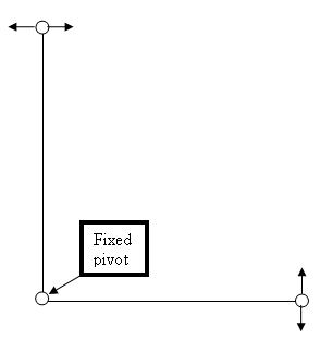
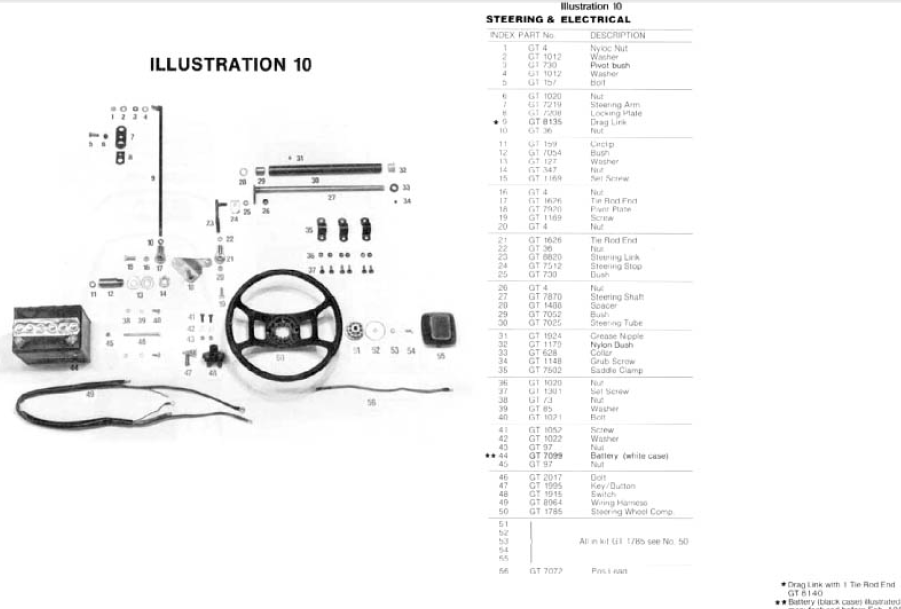
The bell crank translates vertical movements into horizontal movements: when the input arm moves in the direction of the vertical arrows, the output arm moves in the direction of the horizontal arrows. On the mower, when the steering shaft 27 rotates, it moves the steering link 23. The link 23 moves the pivot plate 18. The pivot plate 18 moves the drag link 9. When the steering, and the front wheels, are in the straight ahead position the arm which is part of 27 must be exactly lateral to the mower, and the pivot plate must be in exactly the position the bell crank is in, in the diagram: input arm transverse to the mower, output arm longitudinal to the mower. The pivot plate must move equal amounts from this straight ahead position, when right and left steer are called for. In practice, the bell crank has been altered but from your photograph it looks as if the input and output arms are still at right angles to each other. We don't know whether the drag link has been extended or not. If the drag link is not exactly its original length, the bell crank will have to be moved from its correct position, to make the front wheels face straight ahead. That would give you both assymetrical steering geometry, and an inability to fully turn the front wheels in one direction.
The key question is whether the front wheels are in the straight ahead position when the steering wheel is centred, the steering shaft arm is precisely lateral to the mower, and the pivot plate is also precisely square to the mower. If it is not, you need to adjust the two tie rod ends on the drag link until the wheels are straight ahead when the rest of the steering mechanism is straight ahead.
The steering will not work properly until all of the loose pivots and incorrect geometry are fixed. Any deviation from this parts list is best avoided:
People with substantial experience in making and modifying mechanisms could perhaps do some minor adapting, but doing so would require quite a bit of measuring, drawing and calculating. Even then, the proof of the pudding would not be available until all of the work had been completed and the machine tested carefully. (Note: the top speed of this mower would be about 5 mph and it is for off-road use on private property only - if this were not the case I would reject any suggestion of modification of the steering mechanism.)
I suggest you identify each part from the parts list, note which ones are worn, slack, or not original on your machine, and see what can be done about getting some good parts. These might be new parts from the Greenfield service department, or used parts from a wrecked 12-32 machine. Please report back on the state of your individual steering parts, and we can discuss this further.
Before doing anything to the clutch or its linkage, perform the tensioner-pulley check I described previously. If you find you can move the tensioner up a notch on its ratchet, your drive problem will probably disappear. However in case the problem is still there when the tensioner is pulled up properly, here is what you would do.
Before you draw any conclusions about the condition of your clutches, take a close look at the clutch linkage:
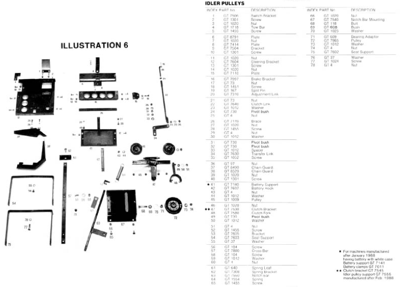
Look particularly at the link (Item 22) and the fork (Item 48) and the mechanism surrounding them. Any wear or slack in these parts would cause the problem you have, without anything being wrong with the clutches themselves. Look also for further tenants' improvements in these parts, similar to what you found with the steering linkage. If, when you have a correctly tensioned drive belt and a sound, firm clutch linkage, correctly adjusted, you have insufficient pedal movement, it will be time to look at the clutch, as described below.
As you noted, the clutch fork has minimal travel. It is supposed to have minimal travel. Unfortunately because of this, on Greenfield clutches quite a small amount of wear on the facings results in losing drive either forward or backward. To fix this it is necessary to remove the cross-shaft on which the pulleys and clutches rotate, and dismantle it. The free movement of the clutches then has to be reduced, which can be done either by replacing the partly-worn clutch facings, or by reducing the stack of shims in the center of the shaft, which sets this clearance. Unfortunately again, your 12-32 has the early "long shaft" design, which means getting the shaft out is a bit more difficult than with the short shaft design that came later.
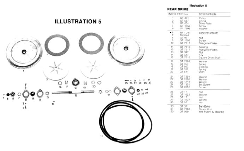
We have several past threads that show in detail how to overhaul the clutches, but before we resort to that, please report back on what you find with the belt tensioning and the clutch linkage.